Periodic inspection
Feasibility checks
Laser Tracker
Serial production workpiece inspection
Template inspection
Workpiece compliance
3D reverse engineering
CAD design
Tool checks
3D digitisation
Machine alignment
Mobile services
Laser Tracker
On-site geometric inspection
Sematec Métrologie’s laser tracker services include on-site metrology services:
• Mapping and dimensional inspection of large-scale workpieces and tools
• Tool setting assistance and periodic checks
• Machine-tool alignment assistance
• Assembly or production line pre-setting and setting assistance
• Comparative surface point inspection with CAD
• Workpiece or assembly scanning for 3D reports and/or for CAD 3D reverse engineering.
Through our 6 French offices, we operate across France and abroad.
Our 3 Hexagon laser trackers allow high-precision tracking of the probing sphere, known as a reflector, using a laser beam.
The measurement uncertainty is approximately +/- 0.05 mm.
Besides inspection services, our technicians are capable of setting tools for compliance purposes by adding foil and applying a mechanical shift to some components.
We work in a variety of manufacturing processes:
machining, sheet metal work, assembly, mechanically welded assembly, thermoforming, composite, etc.
Also, our company, Sematec Métrologie, is open year-round, allowing us to assign our laser tracker technicians on-site during holiday periods (summer and winter), in order to conduct inspections during downtime or machine stoppages.
Measurement arms (probing & scanning)
On-site geometric inspection
Mobile measurement arm services offer the advantage of performing measurements directly on-site in an industrial setting (workshops, factories, air-conditioned laboratories, etc.), without any logistical constraints associated with the weight of the workpieces to be measured, or for confidentiality reasons.
This mobile measurement tool also enables contact or contactless measurements (with probes or scanning heads).
There are many possible applications:
• Mapping and dimensional inspection of workpieces and tools;
• Tool setting assistance and periodic checks
• Small-scale tool or template pre-setting and setting assistance
• Workpiece or assembly scanning for 3D reports and/or for CAD reverse engineering.
• Comparative surface point inspection with CAD
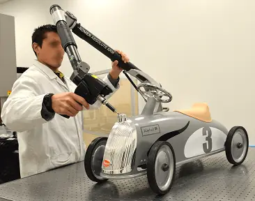
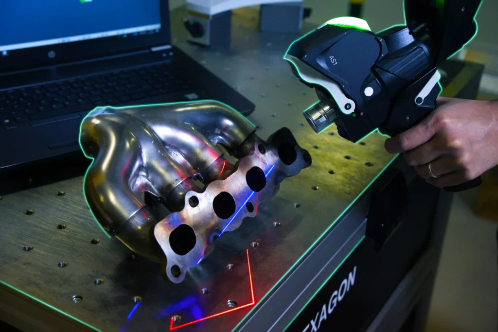
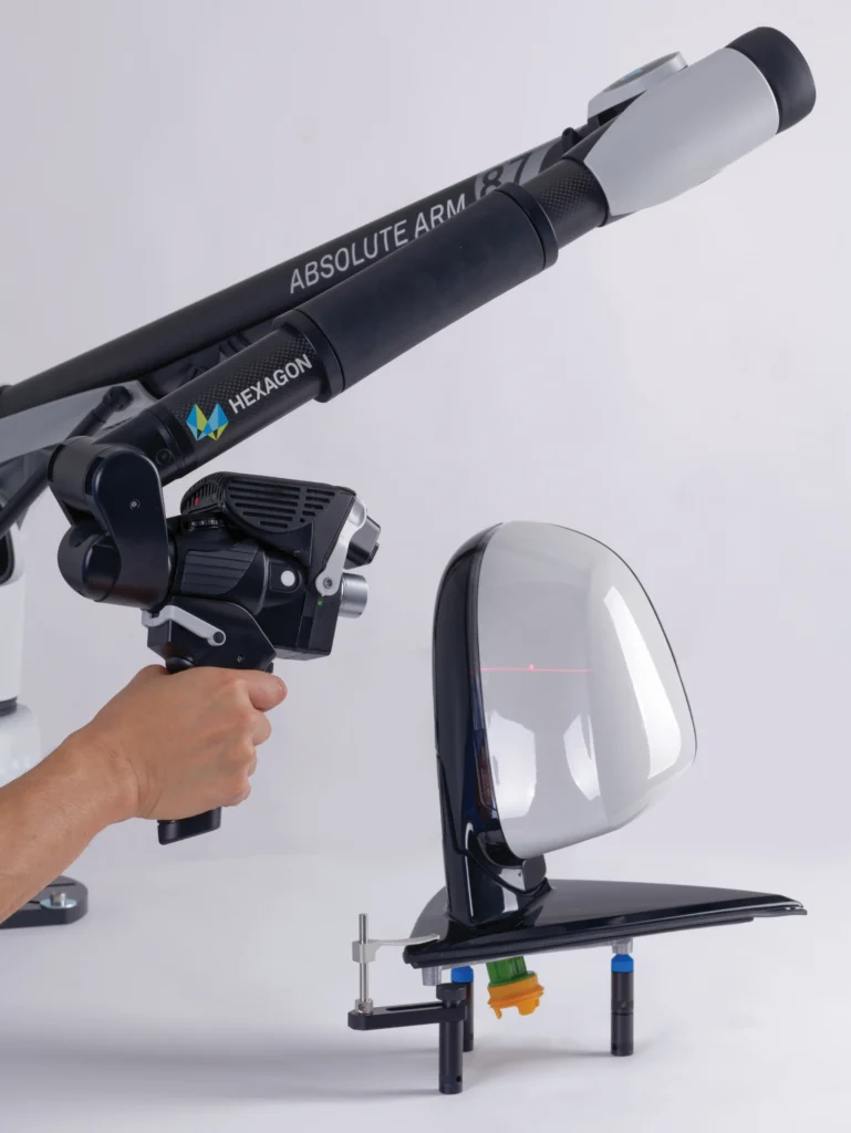
With 6 French offices, we operate across France and abroad.
The Sematec Métrologie group has 9 probing and scanning measurement arms, including one large-scale arm with a range of up to 4.5 m.
The measurement uncertainty is approximately +/- 0.05 mm.
We work in a variety of manufacturing processes: machining, sheet metal work, assembly, mechanically welded assembly, thermoforming, composite, etc.
If you already have your own measurement arms (ROMER, FARO, etc.), we can also assign experienced metrologists on-site to use your equipment.
Also, our company is open year-round, allowing us to assign our technicians on-site during holiday periods (summer and winter), in order to conduct inspections during downtime or machine stoppages.
Reverse engineering
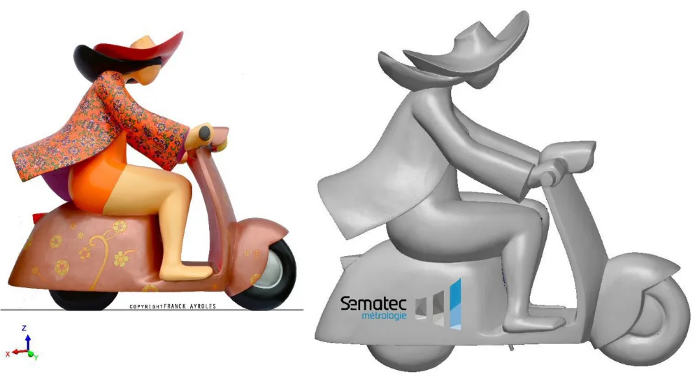
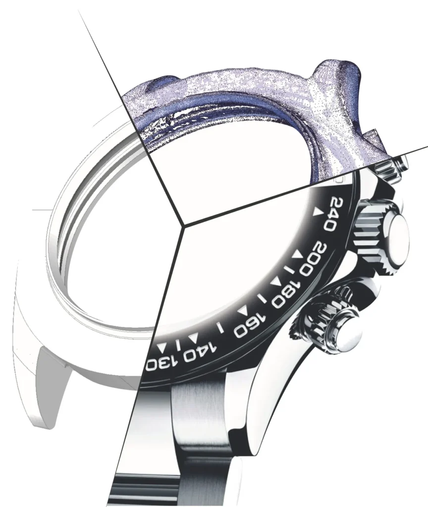
What is reverse engineering?
Aims:
– Obtain the CAD file for a workpiece for which plans are not available or for which you need a file quickly (e.g. prototype).
– View and compare workpiece form errors compared to the nominal CAD file.
– Analyse mould deformations according to wear over time or a change of material.
Step 1: Workpiece 3D Digitisation / Scanning
This process allows you to scan your workpieces to generate a “point cloud” digital model.
Our 3D digitisation resources
We can provide this service with several specialised tools based on workpiece type:
• CT scanning (in air-conditioned laboratory at 20°C).
Used for small-size workpieces requiring high precision, this tool can also be used to digitise internal workpiece surfaces using X-rays. In fact, given that the CT scanner scans the entire workpiece, we can thus access even the most inaccessible surfaces.
• Scanning measurement arm.
Used to model workpieces from a few centimetres to several metres.
This mobile equipment is suitable for use in our laboratories and/or on-site.
• Laser tracker coupled with scanning system.
Used for models of several metres.
This mobile equipment is suitable for use in our laboratories and/or on-site.
Step 2: Reverse engineering
Also known as 3D reconstruction, this step consists of using the digitisation from step 1 to output files compatible with CAD or 3D printing software.
– 3D printing from file in STL format (raw digitisation format)
– CAD reconstruction into multiple recognised formats such as STEP, IGES, CATIA, CREO, SOLIDWORKS, FUSION360.
