X-ray CT scanning
X-ray CT scanning

X-ray CT scanning technology is used to reconstruct the volume of a workpiece (3D point cloud) using X-ray image projections of the object.
Our X-ray technicians can inspect your workpieces using this non-destructive inspection technology (porosities, cracks, inclusions, internal defects, leak detection, fibre visualisation, etc.), and measure workpieces (plastic and aluminium) with a precision of 10+L/50 (or approximately +-12µm).
“If you would like to perform in-house workpiece post-processing, you also have the option of forwarding a 3D scan of your workpiece to us and getting in touch with our teams.
VG studio max volume graphics software is available to purchase; please feel free to ask your point of contact for more details.”
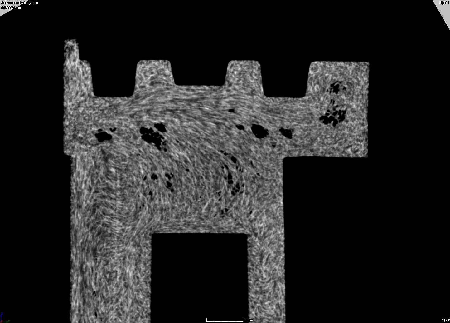
Porosity
Porosity
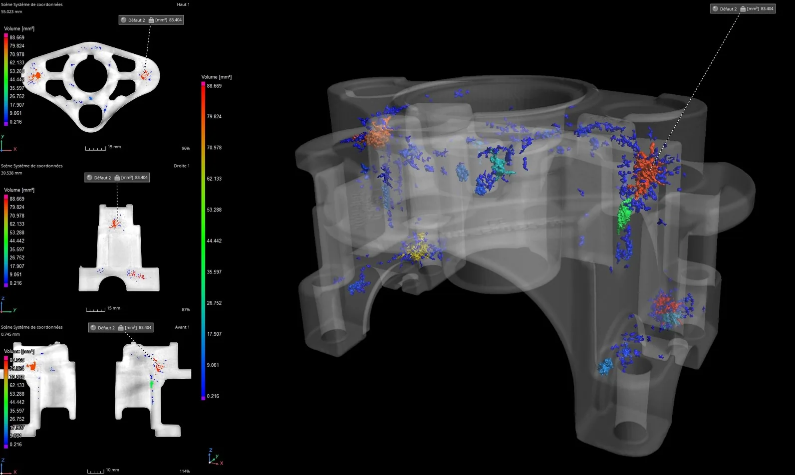
Porosity mapping, void ratio, position, volume, etc.
Inclusion
Inclusion
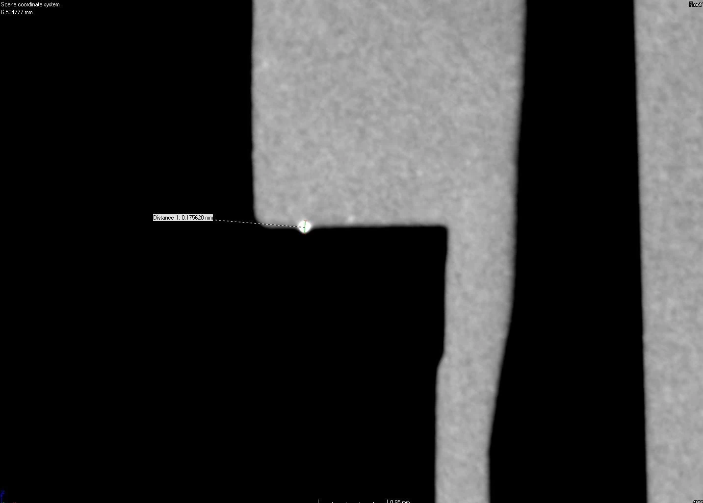
Detection of foreign bodies or unfused material
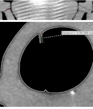
Cracks Burrs
Cracks burrs
CAD Compare or colorimetry
CAD Compare or colorimetry
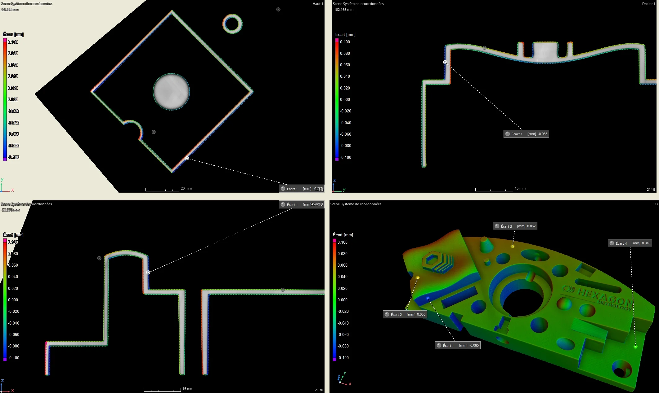
Comparison of CAD or between workpieces
Mapping of wall thickness
Mapping of wall thickness
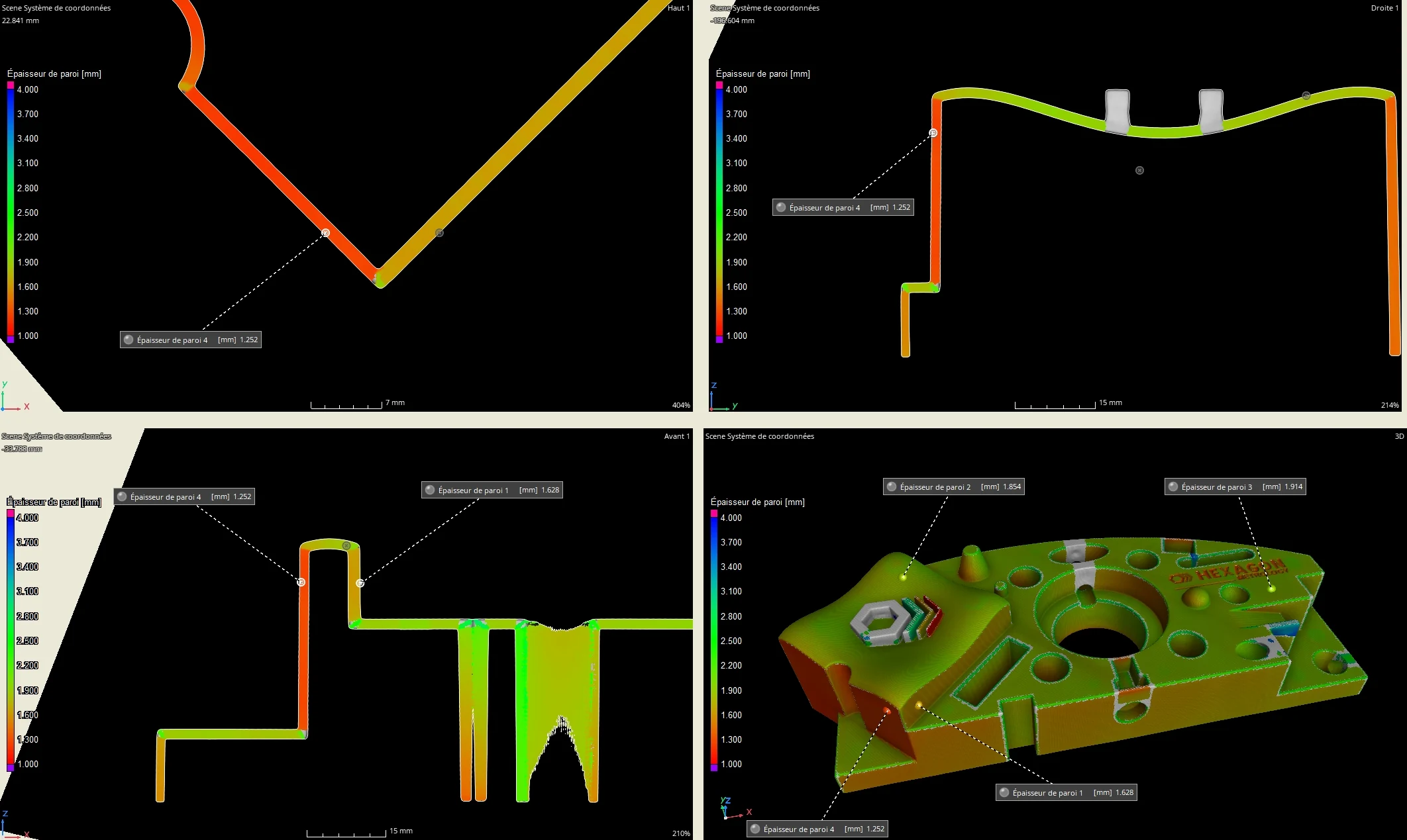
Colour mapping, surface thickness
Metrology and measurement in VG studio max software
Metrology and measurement in VG studio max software
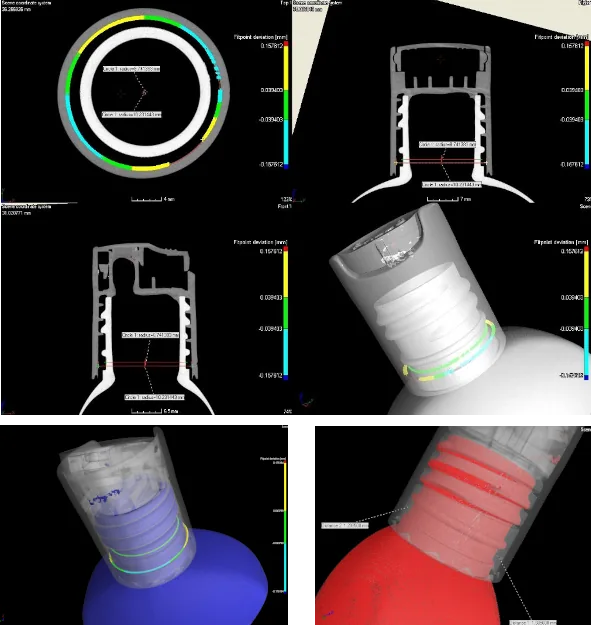
Weld analysis
Weld analysis
Weld zone: Leakage path due to weld defect
Composite
Composite
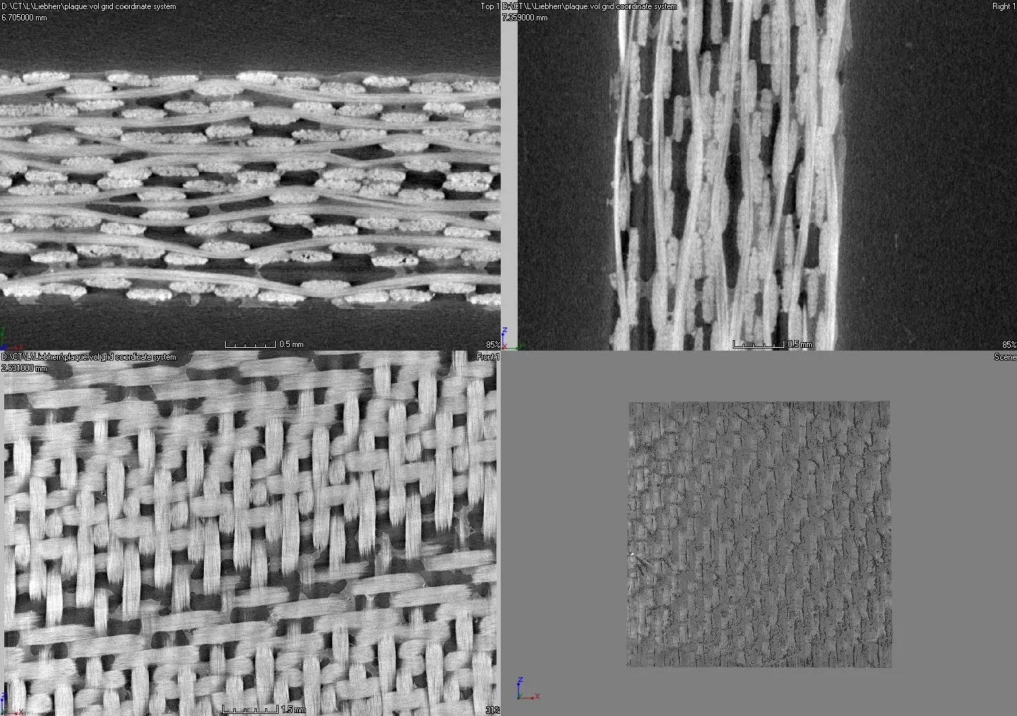
With a resolution of under 10µm, CT scanning reveals composite lattice structures
Glass fibres in plastic injection
Glass fibres in plastic injection
STL
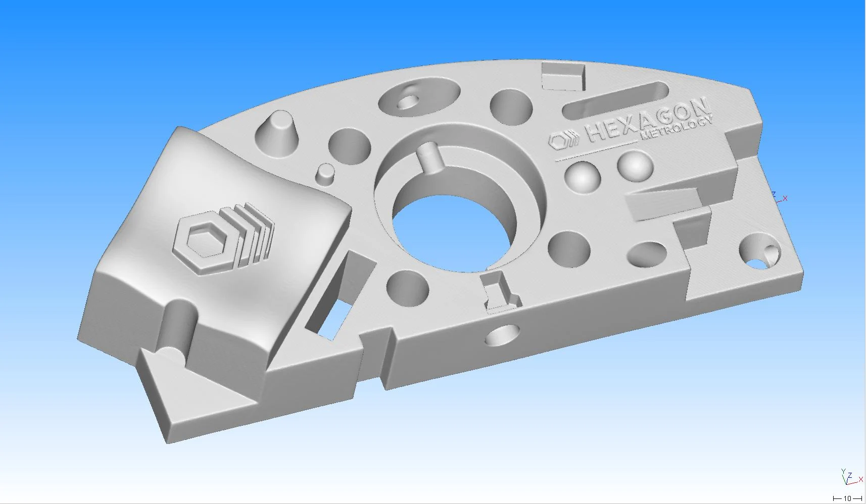
STL
Machine Fleet
Nikon XTH450
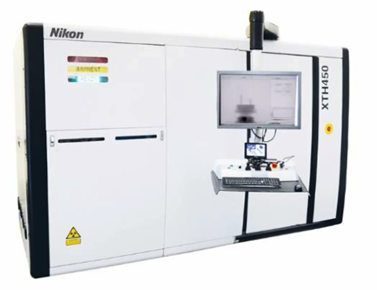
Power 450kv
Maximum acquisition capacity:
cylinder measuring 500 mm in diameter and 600 mm in height
Precision: (15+L)/6
Plastic (density1)
capable of crossing 400 mm of material.
Aluminium (density 2.5)
capable of crossing 200 mm of material.
Steel (density 7.8)
capable of crossing 30 to 50 mm of material.
RX Solution
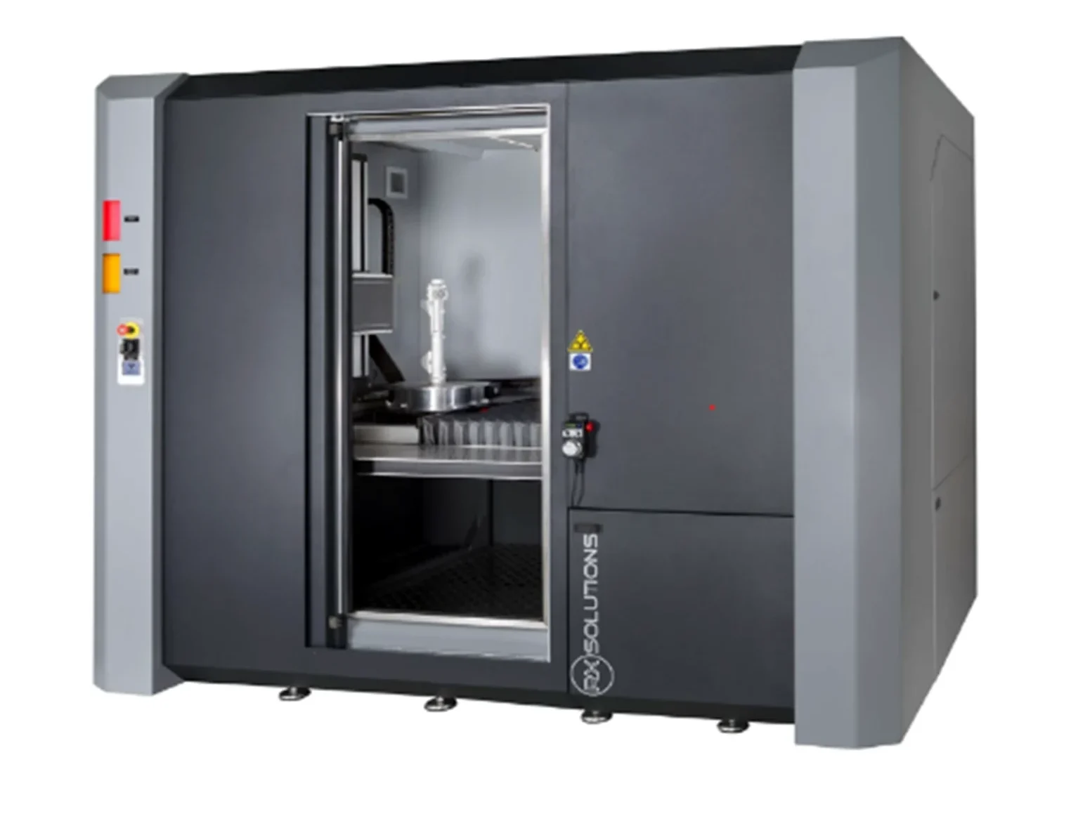
Power 225KV
Maximum acquisition capacity:
cylinder measuring 300 mm in diameter and 700 mm in height
Precision: 9+L/50 (+-10µ to +-20µ)
Plastic (density1)
capable of crossing 300 mm of material.
Aluminium (density 2.5)
capable of crossing 100 mm of material.
Steel (density 7.8)
capable of crossing 5 to 10 mm of material
GE Nano CT 160
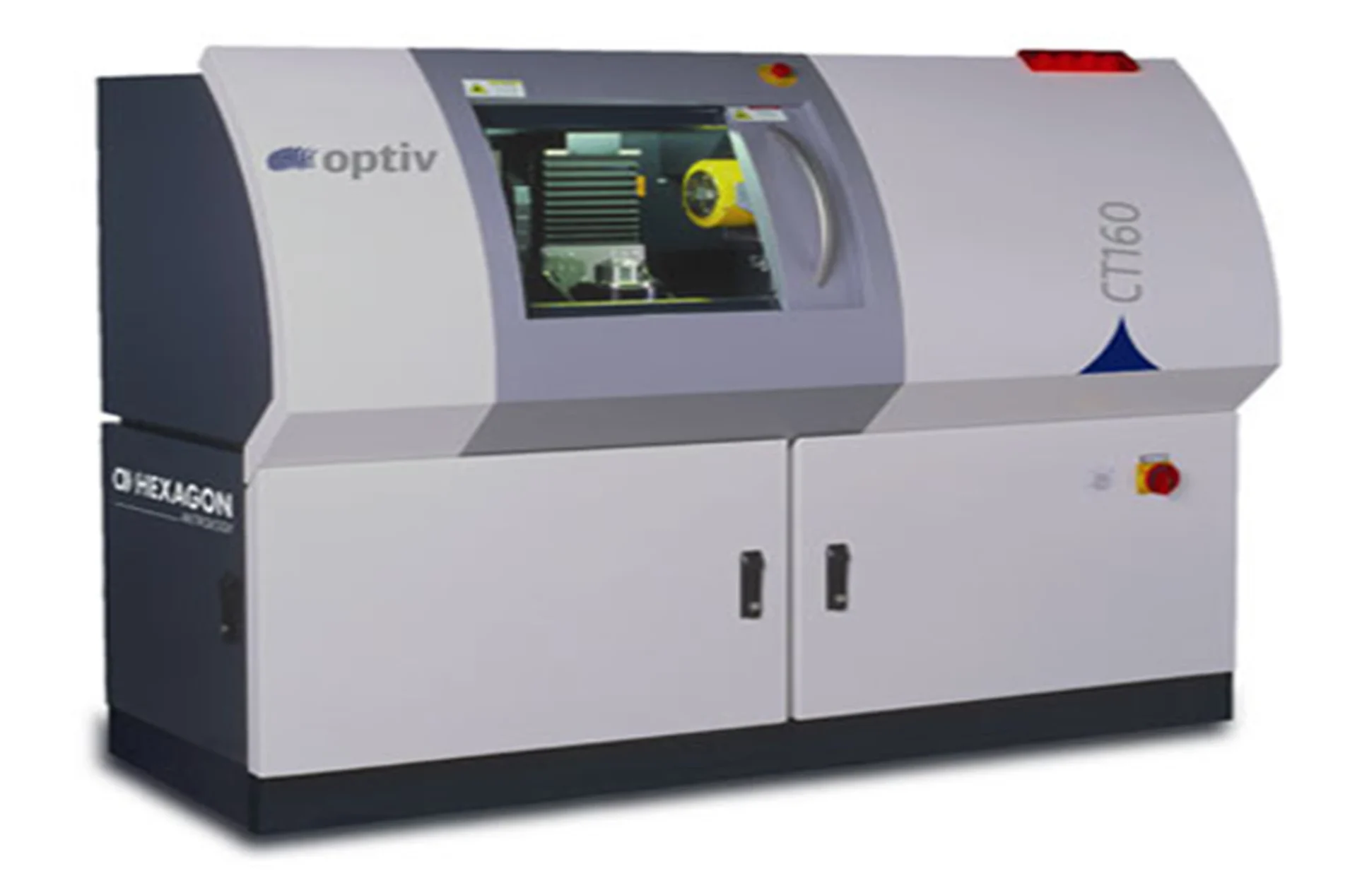
Power 160kv
Maximum acquisition capacity:
cylinder measuring 60 mm in diameter and 60 mm in height
Precision: 9+L/50 (+-10µ to +-20µ)
Plastic (density1)
capable of crossing 100 mm of material.
Aluminium (density 2.5)
capable of crossing 10 mm of material.
Reverse engineering
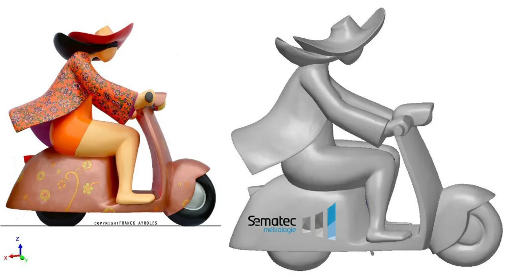
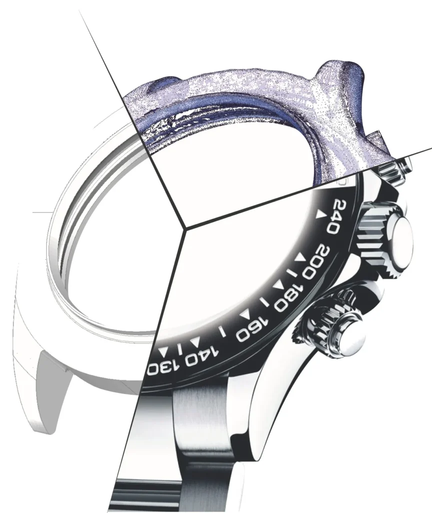
What is reverse engineering?
Aims:
– Obtain the CAD file for a workpiece for which plans are not available or for which you need a file quickly (e.g. prototype).
– View and compare workpiece form errors compared to the nominal CAD file.
– Analyse mould deformations according to wear over time or a change of material.
Step 1: Workpiece 3D Digitisation / Scanning
This process allows you to scan your workpieces to generate a “point cloud” digital model.
Our 3D digitisation resources
We can provide this service with several specialised tools based on workpiece type:
• CT scanning (in air-conditioned laboratory at 20°C).
Used for small-size workpieces requiring high precision, this tool can also be used to digitise internal workpiece surfaces using X-rays. In fact, given that the CT scanner scans the entire workpiece, we can thus access even the most inaccessible surfaces.
• Scanning measurement arm.
Used to model workpieces from a few centimetres to several metres.
This mobile equipment is suitable for use in our laboratories and/or on-site.
• Laser tracker coupled with scanning system.
Used for models of several metres.
This mobile equipment is suitable for use in our laboratories and/or on-site.
Step 2: Reverse engineering
Also known as 3D reconstruction, this step consists of using the digitisation from step 1 to output files compatible with CAD or 3D printing software.
– 3D printing from file in STL format (raw digitisation format)
– CAD reconstruction into multiple recognised formats such as STEP, IGES, CATIA, CREO, SOLIDWORKS, FUSION360.
